nowcarThe electrical system on the computer is getting more and more complex, and understanding the circuit diagram is the basic skill that every good auto mechanic should possess. The following article is compiled by Lao Hou. It systematically describes the classification of automobile electrical circuit diagrams, the characteristics of various circuits, the essentials of reading automobile circuit diagrams, and the methods and precautions of automobile circuit fault diagnosis.
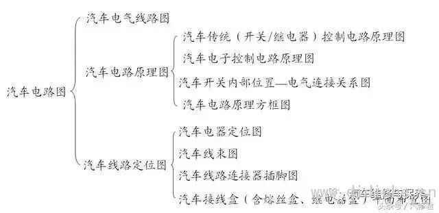
Classification of automotive circuit diagrams
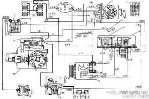
Electrical wiring diagram
Circuit schematic
The circuit schematic diagram focuses on the working principle of each electrical system circuit, which can be the whole car circuit diagram or the circuit schematic diagram of each system
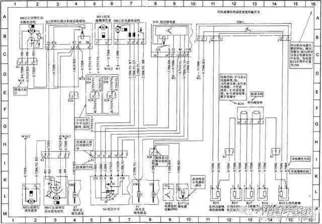
Abscissa type circuit diagram
The circuit diagram of this mode uses the horizontal and vertical coordinates to determine the position of the electrical appliance in the circuit diagram, such asBenzThe car uses numbers as the abscissa and letters as the ordinate to locate the circuit.
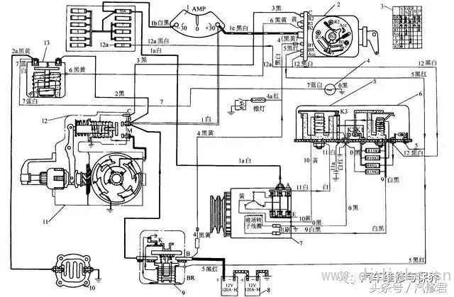
Modular circuit diagram without coordinates
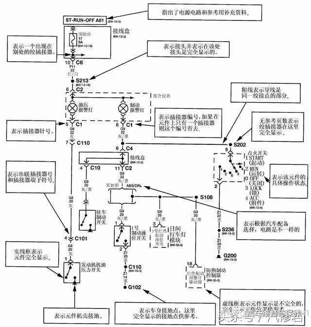
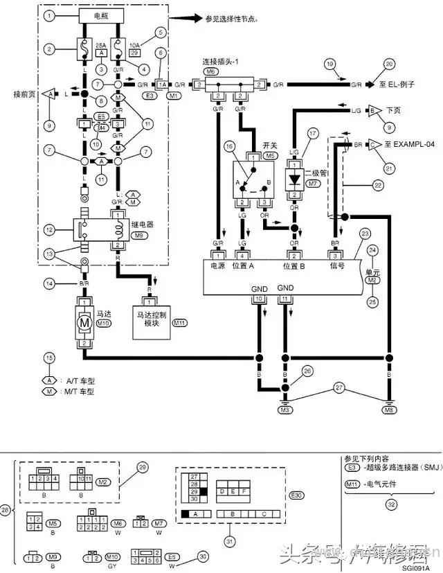
The coordinate-free modular type is not a feature, and it is classified into one category here mainly for comparison with other forms of circuit diagrams. At present, many automobile manufacturing companies adopt this method of drawing, such as GM Buick, Honda, Dongfeng Citroen, Fukang, Toyota, Ford,BMW, Mitsubishi and others. However, the specific circuit expression and graphic symbols of each company are different. When reading the diagram, please refer to the related circuit diagram and graphic symbol list.
Legend 1: Beijing Cherokee (Daimler-Chrysler) circuit schematic

Legend 2: Nissan's circuit schematic
Mitchell circuit diagram
Mitchrll (Mitchrll) is a famous North American companycar repairAs a data supplier, its automotive book products account for 70% of the North American market, and its database CD-ROM products account for 50% of the North American market. The China Automotive Inspection Center signed a database transfer license contract with Mitchell in 1997 and built a full Chinese CVIC car repair database. Mitchell's circuit diagram has become an important material for car maintenance in China.
Features of Mitchell circuit diagram:
⑴ The Mitchell circuit diagram includes the circuit diagrams of major automobile manufacturers in the United States, Europe, and Asia. It is drawn in accordance with a unified format and electrical symbols for easy use.
⑵ In the circuit diagram of the electric control system, the electric control unit is the center, and the pins of the electric control unit are arranged in order according to the code. The components around the electric control unit are roughly at the top of the diagram and the grounding section at the bottom.
⑶ Electrical components are generally around, with wires in the middle.
General essentials for reading automotive circuit diagrams
1. Read the legend several times carefully
The legend shows the names and digital codes of all the electrical equipment of the car. By reading the legend, you can get a preliminary understanding of which electrical equipment the car is equipped with. Then find the electrical equipment in the circuit diagram through the digital code of the electrical equipment, and further find out the mutual connection and control relationship.
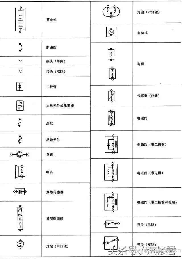
2. Keep in mind the electrical graphic symbols
The car circuit diagram uses electrical graphic symbols to express its composition and working principle. Therefore, you must keep in mind the meaning of the circuit graphic symbols in order to understand the circuit schematic.
3. Memorize the circuit marking symbols
In order to facilitate the drawing and reading of automobile electrical circuit diagrams, some electrical devices or their terminals are given different logo codes.
4. Keep in mind the characteristics of automotive circuits
The characteristics of automotive circuits are:
⑴ Single wire system
⑵ Negative grounding
⑶ Electric equipment in parallel
5. Keep in mind the loop principle
Any complete circuit is composed of power supply, fuse,switch, Control devices, electrical equipment, wires, etc. The current flow must start from the positive pole of the power supply, pass through fuses, switches, control devices, wires, etc. to reach the electrical equipment, and then return to the negative pole of the power supply through the wires (or ground) to form a loop. Therefore, when reading the circuit diagram, there are three ideas:
Idea 1: Follow the current flow of the circuit, start from the positive pole of the power supply, follow the path to find the electrical equipment, switches, control devices, etc., and return to the negative pole of the power supply.
Idea 2: Against the direction of the current in the circuit, start from the negative pole (grounding) of the power supply and return to the positive pole of the power supply through electrical equipment, switches, control devices, etc.
Idea 3: Starting from the electrical equipment, search for its control switch, wiring, and control unit in turn, and reach the positive pole of the power supply and the ground (or the negative pole of the power supply).
In practical applications, different ideas can be selected depending on the specific circuit, but one thing is worth noting: With the widespread application of electronic control technology in automobiles, most electrical equipment circuits have both a main loop and a control loop, and both loops must be taken into account when reading the diagram. .
6. Browse the whole picture and divide each unit system
To understand the car circuit diagram, you must first master the basic functions and electrical characteristics of the various electrical components that make up the circuit. On the basis of roughly grasping the basic principles of the whole picture, separate the unit system circuits one by one, so that it is easy to grasp the main functions and characteristics of each part.
When framing each system, you must abide by the principle of loops. Note that neither the components in each system nor the components of other systems can be framed. The general rule is:
Only the power supply and the main switch of each electrical system are public, and any other system should be a complete and independent electrical circuit, including power supply, switch (fuse), electrical appliances (or electronic circuits), wires, etc. From the positive pole of the power supply through the wire, switch,fuseAfter the electrical appliance is grounded, it will return to the negative pole of the power supply.
7. Memorize the internal connections and interrelationships between the local circuits
From the perspective of the entire vehicle circuit, each partial circuit is relatively independent except for the power supply circuit, but there are also internal connections between them (such as signal sharing). Therefore, when recognizing pictures, not only must be familiar with the composition, characteristics, working process and current flow path of each partial circuit, but also understand the connection and mutual influence between each partial circuit. This is a necessary condition for quickly finding the fault location and troubleshooting.
8. Master the role of various switches in the circuit
For switches with multi-layer and multi-gear terminal blocks, the functions of each level and block of each block should be analyzed level by level, by gear position, and by terminal block.Some electrical equipment is subject to more than two single-shift switches (orRelay) Control, some are controlled by more than two multi-speed switches, and its working state is more complicated. When there are many switch terminals, first grab one or two terminals from the power supply, and then analyze the gears of the electrical equipment connected to the other terminals one by one to find out the control relationship.
For the combination switch, the actual circuits are together, and they are drawn in the respective partial circuits according to their functions in the circuit diagram. In this case, you must carefully study and read them.
9. Comprehensive analysis of the initial state and working state of switches and relays. In the circuit diagram, various switches and relays are drawn according to the initial state. That is, the button is not pressed, the switch is not turned on, the relay coil is not energized, and its contact is not closed (referring to the normally open contact). This state is called the original state. When recognizing the picture, it is not possible to analyze the original state completely, otherwise it is difficult to understand the working principle of the circuit, because most electrical equipment changes the circuit through the change of switches, buttons, and relay contacts, and then realizes different circuit functions. . Therefore, it is necessary to analyze the working status.
10. Grasp the position of electrical devices in the circuit diagram
A large number of electrical devices are combined with electromechanics. When they are displayed on the circuit diagram, manufacturers often use centralized or separate representations according to the actual situation in order to make the drawing method simple (to facilitate drawing) and to facilitate the identification of the drawing.
Centralized representation is a representation method that draws together the various components of an electrical device on a diagram. This method is only suitable for simpler circuits.
Separate representation, such as drawing the coils and contacts of the relay in different circuits, and linking the separated parts with the same text symbol or number symbol.
11. Easy first and difficult later
Some partial circuits of some automobile circuit diagrams may be complicated and difficult to understand for a while. You can temporarily put them away. After the other partial circuits are understood, combine to understand the relevant information related to the circuit in the figure, and then go further. Read this part of the circuit.
12. Pay attention to collecting information and experience accumulation
For circuits that you can’t understand, you should be good at consulting relevant personnel, and at the same time good at finding and collecting relevant information; pay attention to in-depth study of typical automotive circuits to achieve analogy; pay special attention to the accumulation of actual work experience, the application and innovation of new technologies and new processes.
13. Image reading method of automobile electronic control system
There are more and more automobile electronic control systems. In addition to the above-mentioned methods, the following methods and steps are very helpful for the reading of automobile electronic control systems.
1. Take the ECU of the electronic control system as the center, because this is the control center of the entire system, and all electrical components must have a relationship with this.
2. Have a general impression of the pins of the ECU, and figure out the rules of pin arrangement in several areas.
3. Find out which power lines the system supplies to the ECU. Note that there is generally more than one power line for ECUs, and figure out the power supply status of each power line (such as normal fire line or switch control).
4. Find out the grounding wires of the system, and pay attention to distinguishing which are grounding in the ECU, which are grounding on the frame, and which are grounding on the body of each assembly.
5. Find out which are the signal inputs of the systemsensor,eachsensorDo you need power, and find out the corresponding power cord, where the sensor is grounded.
6. Find out the actuators of the system, find out the power supply and grounding situation, and how the computer controls the actuator (control grounding end or power end).
carWire harness
Automotive wire
According to the level of withstand voltage: high-voltage wire and low-voltage wire.
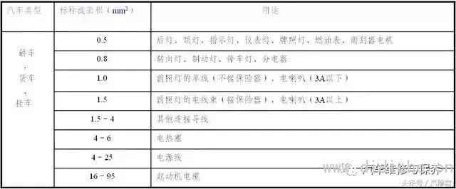
⑴ Correct choice of wire cross-sectional area
Choose the cross-sectional area of the wire according to the load current of the electrical equipment. The general principles are:
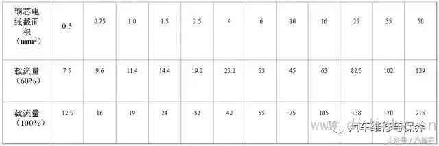
Electrical equipment that works for a long time can choose wires with an actual carrying capacity of 60%; electrical equipment that works for a short time can choose wires with an actual carrying capacity between 60% and 100%. At the same time, the voltage drop in the circuit and the heating of the wire should also be considered, so as not to affect the electrical performance of the electrical equipment and exceed the allowable temperature of the wire. In order to ensure a certain mechanical strength, the cross-sectional area of the low-voltage wire is generally not less than 0.5mm2.
The following table shows the allowable current-carrying capacity of the nominal cross-sectional area of various copper core wires.
The following table is the recommended value for the selection of the cross-sectional area of the main circuit wire of the automobile 12V electrical system.
⑵ The color of the wire
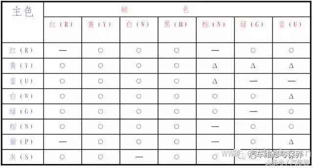
In order to facilitate installation and maintenance, the car adopts two-color wires, the main color is the basic color, and the auxiliary color is a ribbon or spiral ribbon with looped wires. The main color is in the front and the auxiliary color is in the back when marked. When selecting on the basis of two-color, the power cord of each power system is single-color, and the rest are two-color. The main colors of the two-color lines are shown in the table below.
For two-color lines with a nominal cross-sectional area greater than 1.5 mm2, the matching of main and auxiliary colors is shown in the table below.
Note: ○-Allowed matching colors; Δ-Not recommended matching colors.
factory reset
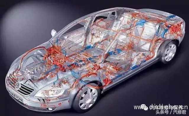
In order to make the whole car line regular, easy to install and to protect the insulation of the wire, the whole car line on the car exceptHigh-voltage line,AccumulatorCable andstarterOutside the cable, the wires of different specifications in the same area are usually wrapped with cotton yarn or thin PVC tape into a bundle, which is called a wire harness.
⑴ Bandaging of wire harness
① The cable half-folding method, coating insulating paint, and drying to increase the strength and strength of the cable
Insulation performance.
② The new type of wiring harness is partially wrapped with plastic and put into the side-cut plastic corrugated pipe to make it stronger, better in protection, and easy to find line faults.
⑵ Wiring harness installation. After the wiring harness of the same vehicle type is designed and manufactured in the manufacturer according to the vehicle type, it is fixed to the predetermined position on the vehicle with a circlip or trip nail. The number is installed on its corresponding terminal. The wiring harnesses of various models are different, and the wiring harness of the same model is divided into multiple wiring harnesses according to the engine, chassis and body.
Common faults of automotive electrical equipment lines
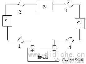
Open circuit (open circuit) fault
Short circuit (short circuit) fault
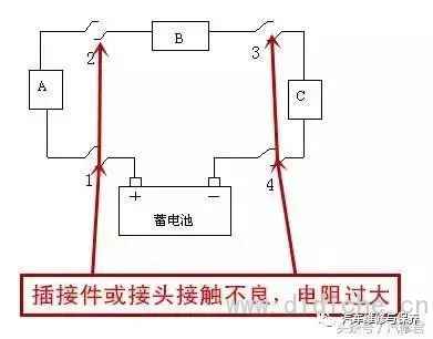
Poor contact (contactresistanceToo large) fault
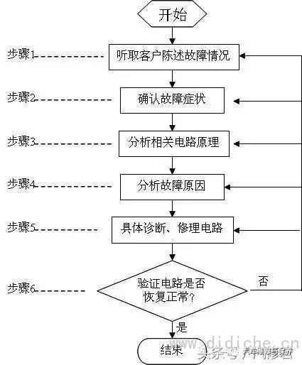
The general process of automobile circuit fault diagnosis and overhaul
The general process is helpful for beginners to follow the steps step by step and cultivate good fault diagnosis and maintenance ideas. For maintenance personnel with considerable theoretical knowledge and work experience, there is no need to be too constrained to the process steps in actual work. Some steps can be skipped according to the actual situation or experience, and the fault point can be checked and repaired directly, which can effectively improve work efficiency.
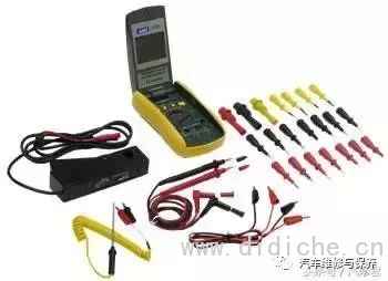
In addition, there are more and more microcomputer control systems on modern cars, which use faultsDiagnostic instrumentReading fault codes and data streams for fault diagnosis is very fast, which can effectively reduce the scope of the fault and even directly complete the fault location. Therefore, for microcomputer control system faults or related faults, pay attention to the priority of the fault diagnosis instrument.
Common methods for fault diagnosis and maintenance of automobile lines
Intuitive method
When a certain part of the car's electrical system fails, there will be abnormal phenomena such as smoke, sparks, abnormal noise, burnt smell, and high temperature. Through the human body's sensory organs, listening, touching, smelling, seeing, etc., the car electrical appliances are visually inspected, and then the location of the fault can be judged, thereby greatly improving the inspection speed.
Check insurance law
When the car's electrical system fails, first check whether the insurance is intact. For example, when a car is driving, if an electrical appliance suddenly stops working and the fuse on the branch is blown, it indicates that there is a ground fault in the branch. If the fuse of a certain system is repeatedly blown, it indicates that the system must have a fault similar to grounding, and the fuse should not only be replaced.
Scrape
Scrape method, also known as fire test method, is usually used to determine whether the wiring harness or wire has an open circuit. Remove a wire end of the electrical equipment and touch the metal part (iron) of the car, and judge whether there is an open circuit according to the presence or absence of sparks.
Note: Scrape should not be used to check the electronic circuit of the car, so as not to damage the electronic components and equipment.
Light test
Use oneCar bulbAs a temporary light test, check whether the wiring harness is open or shorted, and whether there are faults in electrical appliances or circuits, etc. This method is particularly suitable for checking electrical appliances with electronic components that do not allow direct short circuits. When using the temporary lamp test method, pay attention to the power of the test lamp not to be too large. When testing the control (output) of the electronic controllerTerminalBe especially cautious when there is output and whether there is enough output to prevent overloading and damage to the controller.
Short circuit method
The short-circuit method is also called the short-circuit method, that is, use a wire to short-circuit a certain section of wire or an electrical appliance and observe the changes in the electrical appliance.
Substitution method
The replacement method is often used in situations where the cause of the fault is more complicated, and the possible causes can be eliminated one by one. The specific method is to replace a component that is considered to be or suspected to be faulty with a component that is known to be intact, so as to test whether the suspicion is correct. If the fault is eliminated after replacement, the suspicion is established; otherwise, replace the original with a new replacement until the real fault is found.
Simulation method
⑴ Vehicle vibration simulation
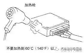
⑵ Thermal sensitivity (temperature) simulation
Note: Do not heat electrical components above 60°C.
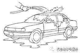
⑶ Immersion simulation
Note: Do not spray water directly on electrical components.
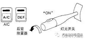
⑷ Electric load simulation
⑸Cold start or hot start simulation
In some cases, electrical faults only occur when the vehicle is cold-started, or when the vehicle is briefly turned off and then warm-started.
Precautions for fault diagnosis and maintenance of automobile lines
The first principle for repairing the electrical system of a car is not to change wires or electrical appliances at will. This operation may cause a fire due to a short circuit or overload. At the same time, pay attention to the following items:
1
When removing the battery, always remove the negative (-) cable first; when installing the battery, always connect the negative (-) cable last.When removing or installing the battery cable, make sureIgnition SwitchOr other switches have been disconnected, otherwise it will cause damage to the semiconductor components. Do not reverse the polarity of the battery terminal.
2
It is allowed to use ohmmeters and multimeters with low resistance ohms below R×100 to detect low-power transistors, so as not to damage them due to current overload. When replacing the transistor, the base should be connected first, and when disassembling, the base should be disassembled last. For the metal oxide semiconductor tube (MOS), the electrostatic breakdown should be caused. When soldering, the soldering iron plug should be unplugged from the power supply.
3
When removing and installing components, the power supply should be cut off. If there is no special instructions, the distance between the component leads and the solder joints should be more than 10mm to prevent the soldering iron from damaging the components, and an electric soldering iron with a constant temperature or a power of less than 75W should be used.
4
When replacing a burnt-out insurance, the insurance of the same specification should be used. Using an insurance larger than the specified capacity can cause electrical damage or fire.
5
The part of the wiring harness close to the vibrating component (such as the engine) should be fixed with a clip, and the slack part should be tightened to prevent the wiring harness from contacting other parts due to vibration.
6
Don't treat electrical appliances roughly, and don't mess around at will. No matter the device is good or bad, it should be handled with care. So as not to withstand excessive impact.
7
The part of the harness that is rubbed against the sharp edge should be wrapped with tape to avoid damage. When installing fixed parts, make sure that the wiring harness is not pinched or damaged, and at the same time, make sure that the plug is firmly connected.
8
During maintenance, if the temperature exceeds 80°C (such as during welding), the temperature-sensitive parts (such as ECU) should be removed first.






 Email: